Voltage Stability in the Age of DERS: The Case for Centralised, Wide Area Voltage Management
As distribution grids evolve into dynamic, decentralised systems dominated by DERs and flexible demand, voltage control is undergoing a transformation.
Introduction: The Distribution Grid Under Transformation
The rise of decentralised energy resources (DERs) is fundamentally transforming the structure and behaviour of the distribution grid. What was once a passive, predictable system is evolving into a dynamic, active distribution grid, with control complexity rivalling that of the transmission system.
Historically, voltage control was largely a top-down function. Transmission grids provided voltage support, cascading down through substations with On-Load Tap Changers (OLTCs) and bulk reactive power compensation. The distribution system—at the tail end of this hierarchy—required only limited, localised intervention. Conventional devices like capacitor banks and voltage regulators were deployed to manage voltage drops associated with passive, largely resistive loads. With predictable, unidirectional power flow from source to sink, voltage regulation was straightforward and required minimal coordination.
But that regime no longer holds. As illustrated on the right side of Figure 1, the modern distribution grid incorporates diverse, embedded resources—from solar and battery storage to electric vehicles and renewables. These components operate not only as loads but also as generators or flexible assets.
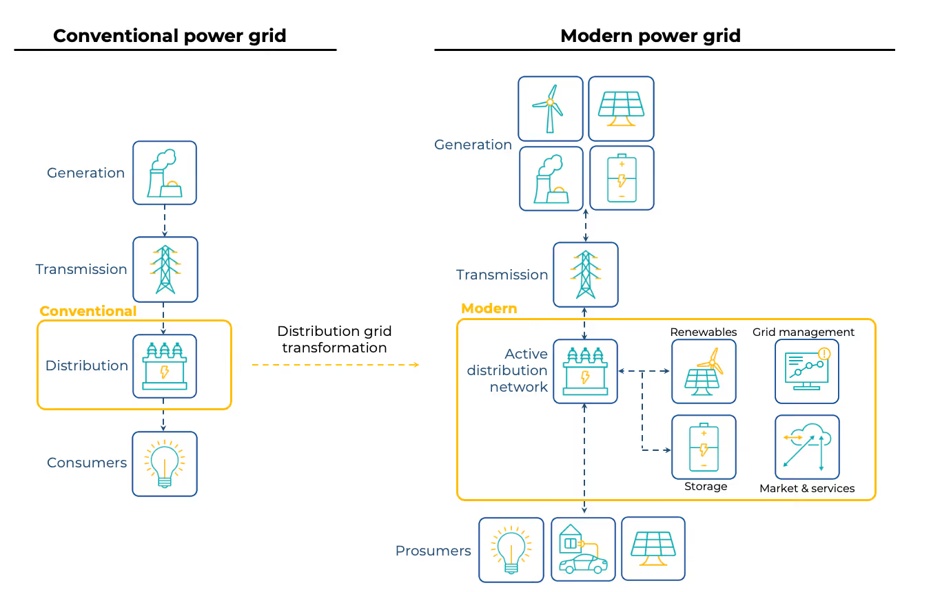
This increasing bidirectional and stochastic behaviour undermines the assumptions on which legacy voltage control strategies were based. Variability is no longer temporal alone—it’s also spatial. Maintaining voltage within narrow limits now requires real-time visibility, coordination, and enhanced control strategies. To address this complexity, distribution grids must shift from passive infrastructure to coordinated, adaptive voltage management systems. Voltage regulation is no longer secondary—it has become a primary operational objective, central to maintaining reliability, power quality, and resilience in an increasingly electrified and decarbonised world. This includes coordinating inverter-based resources, controlling flexible demand, and deploying advanced grid analytics. It also demands an architectural shift: from deterministic planning toward data-driven, probabilistic, and distributed control paradigms.
New Voltage Profiles in Active Distribution Grids and Existing Control Methods
As distribution grids become more decentralised, voltage regulation emerges as one of the most critical operational challenges. In the conventional setting—characterised by unidirectional power flow and predictable load curves—voltage naturally declined along the feeder. In this context, voltage support was relatively straightforward and managed through tap-changing transformers, mid-feeder voltage regulators, and fixed or switched capacitor banks.
However, in modern grids with high penetration of DERs, this assumption breaks down. Photovoltaic systems and battery inverters, often located near the end of feeders, inject active power in directions opposite to the traditional flow, creating bidirectional and time-varying voltage profiles. As seen in Figure 2, the presence of DERs can cause localised over-voltages—a phenomenon where the voltage rises above statutory limits at points far from the substation, especially under low-load, high-generation conditions.
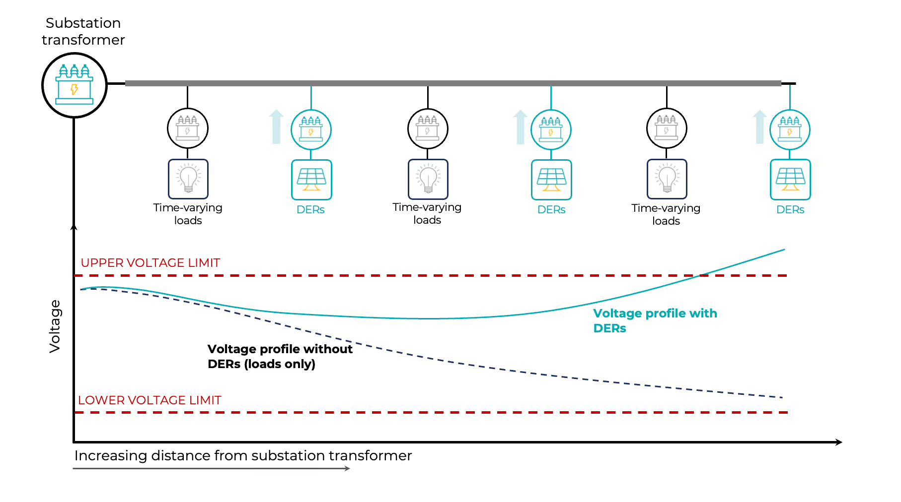
The core issue arises from the dynamic interaction between time-varying loads and decentralised generation, each responding independently to local conditions. This can result in a fragmented and unstable voltage landscape, particularly when communication or coordination among devices is lacking.
To address this, utilities still rely on a combination of (uncoordinated) conventional, converter-based, and network-level control methods—summarised in Figure 3. Each method targets voltage regulation at different spatial and temporal scales:
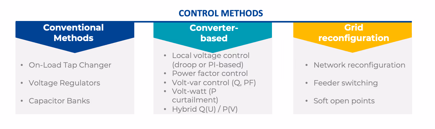
- Conventional methods—including OLTCs, voltage regulators, and capacitor banks—have traditionally served as the backbone of voltage control in distribution grids. These devices operate at the primary or secondary substation level and along key feeder locations, offering bulk reactive power support to counteract voltage drops during peak loading conditions. However, their performance is optimised for slow-moving, unidirectional load profiles. They lack the temporal responsiveness and spatial granularity needed to address fast-changing, localised voltage issues introduced by DERs. For instance, OLTCs respond on the scale of tens of seconds to minutes and cannot resolve over-voltages caused by momentary solar injections at distant feeder ends.
- Converter-based methods leverage the fast-acting capabilities of inverter-based DERs, such as PV systems and battery energy storage. These resources can be programmed to implement autonomous voltage control functions, such as Volt-VAR (reactive power compensation based on local voltage), Volt-Watt (active power curtailment during high-voltage events), and hybrid Q(U)/P(V) strategies. These methods excel in providing localised voltage support without requiring communication infrastructure. However, when widely deployed without coordination, they can interact nonlinearly, leading to instability, oscillations, or excessive curtailment, especially in dense DER clusters.
- Grid reconfiguration provides a network-level voltage management mechanism by altering the topology of the distribution grid. This is typically done through feeder switching, tie-line operations, or the deployment of soft open points—devices that allow flexible interconnection between feeders. By rerouting power flows, utilities can redistribute voltage gradients, reduce feeder loading, or isolate problematic zones experiencing voltage excursions. While not instantaneous, reconfiguration is increasingly being integrated into ADMS platforms as part of Volt/VAR Optimisation (VVO) and automated contingency response schemes. It offers a complementary layer of control, especially valuable in constrained or weakly meshed networks.
- Voltage control methods in active distribution networks can be deployed at various levels of granularity and coordination, each with distinct architectural and operational characteristics. These levels—local, distributed, and centralised—determine how control actions are initiated, where measurements are taken, and how different devices interact (or don’t) across the system. Figure 4 illustrates these four paradigms, using a common layout of inverter-connected DERs (PV, EV chargers, and storage) interfacing with the grid at different levels of control sophistication.
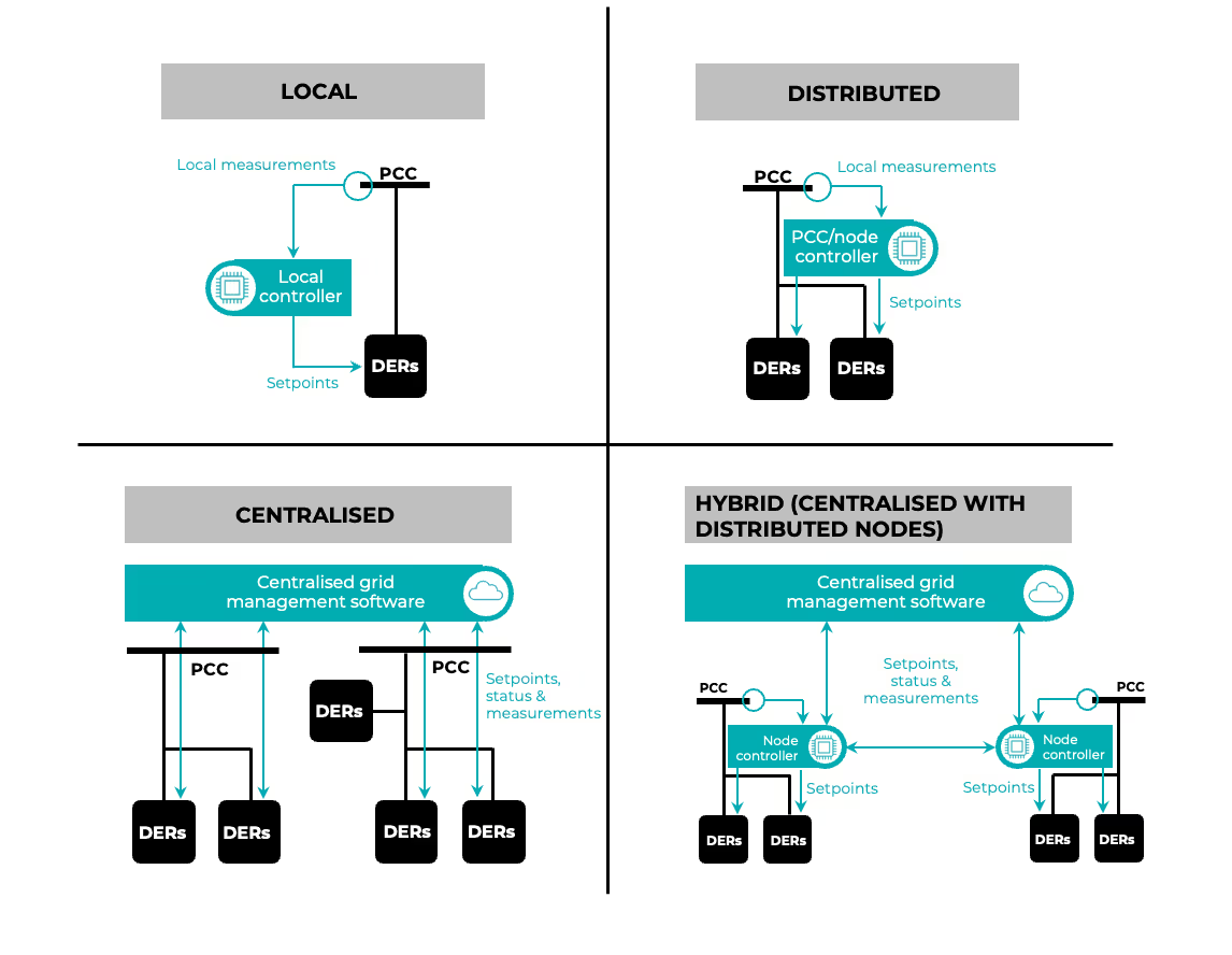
- Local Voltage Control: In the local control architecture, each DER operates autonomously based solely on local voltage measurements at the point of common coupling (PCC). The embedded controller (typically within the inverter) implements predefined strategies such as Volt-VAR, Volt-Watt, power factor, or droop control, adjusting its real or reactive power output without any external coordination. This model offers excellent scalability and responsiveness, requires no communication infrastructure, and is inherently robust to faults or latency. However, it lacks system-level optimisation and can lead to unintended interactions, particularly in areas with high DER penetration or fast-changing voltage conditions. For instance, when several inverters respond independently to the same voltage deviation, their combined reactive power adjustments can overcompensate, producing oscillatory or unstable voltage behaviour rather than restoring equilibrium.
- Distributed Voltage Control: Distributed control introduces a layer of local coordination across groups of DERs, often at the feeder or node level. Here, a PCC-level or node controller aggregates local measurements and optimises setpoints for multiple devices within its scope. This enables more coherent control responses, such as reducing redundant reactive power actions or avoiding conflicts between adjacent inverters. Distributed control strikes a balance between scalability and performance: it does not require full system observability but still improves voltage profiles across localised sections of the grid. It is particularly effective in microgrids, feeder groups, or active zones, and can function with limited communication bandwidth or edge-based intelligence.
- Centralised Voltage Control: In the centralised architecture, voltage control is orchestrated by a single, grid-wide management system—such as an ADMS or SCADA. These platforms gather real-time data across the network, perform global optimisation (e.g. Volt/VAR optimisation or loss minimisation), and dispatch setpoints to DERs, voltage regulators, or storage units accordingly. Centralised control offers the highest level of system efficiency and coordination, capable of proactively preventing violations and integrating with market mechanisms for procuring ancillary services. However, it relies heavily on communication infrastructure, data integrity, and latency management, making it more vulnerable to cyber risks or loss of visibility during contingencies. Note that not all centralised voltage control schemes are equivalent—later sections of this article, including Figure 7, demonstrate how advanced coordination platforms such as WAVO differ significantly from traditional centralised approaches in performance and impact.
Orchestrating Voltage Control: Challenges
The increasing deployment of decentralised voltage control methods—ranging from local Volt-VAR curves to feeder-level distributed strategies—has improved the responsiveness of distribution grids. Yet, the lack of unified orchestration is emerging as a core weakness. As active networks grow in complexity, coordination failures, instability, and conflicting control actions are becoming more common and more impactful.
COORDINATION FAILURES:
A well-documented issue in active distribution systems is the unintended interaction among autonomous controllers. When inverters operate on independent Volt-VAR or Volt-Watt curves, especially in dense clusters, their actions can compound or counteract each other. This can lead to voltage oscillations, control loop hunting, or excessive curtailment that undermines both voltage stability and DER efficiency.
Figure 5 provides a clear example of such a coordination failure. In this scenario, one group of DERs injects reactive power based on constant-power factor setting (this is a business-as-usual regime) leading to over-voltages, while another group simultaneously absorbs reactive power to resolve over-voltage conditions elsewhere on the feeder. Without a centralised or hierarchical controller to orchestrate these actions, the net result can be increased over-voltages, conflicting flows, and wasted reactive capacity.
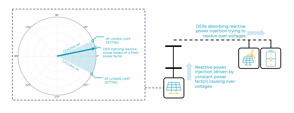
Even in distributed schemes, where local coordination is attempted (e.g., feeder-based aggregators or PCC-level controllers), there is often no clear hierarchy for resolving conflicts between layers or across feeder boundaries. Overlapping control loops—for example, between a mid-feeder voltage regulator and downstream smart inverters—can create sluggish or oscillatory behaviour if not properly sequenced or stabilised.
MULTI-TIME SCALE COORDINATION FAILURES:
A crucial architectural principle for stable voltage control is the adoption of multi-time scale strategies. Fast-reacting inverter-based DERs can provide near-instantaneous voltage support, but must be harmonised with slower-acting devices, such as OLTCs and capacitor banks, which operate on the scale of seconds to minutes. Without a coordinated temporal hierarchy, fast devices may constantly counteract the slow ones, or vice versa—leading to either instability or inefficiency.
THE GAPS IN STANDARDISATION & FRAMEWORKS
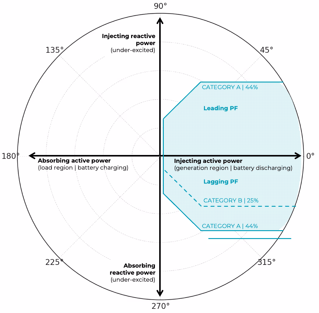
A range of standards, grid codes, and regulatory schemes have emerged globally in an effort to standardise how DERs support voltage regulation, especially in systems with increasing inverter-based penetration. Among these, the implementation of IEEE Std 1547-2018 has sharpened the discussion on how DERs should provide voltage and reactive power support. The standard requires DERs to operate across multiple quadrants of active and reactive power injection or absorption, with different performance obligations depending on whether they are classified as Category A or Category B devices (Figure 6). Category A DERs meet only the minimum requirements, while Category B DERs extend this with stronger reactive absorption capability and additional modes such as Volt-Watt and Watt-VAR.
While this technical framework ensures that inverters have the basic functionality to support distribution grids, it also exposes several practical challenges. The key issues are:
- DER category assignment — determining when Category B capabilities are necessary, which is often a regulatory rather than purely technical decision.
- Control mode selection and parameter tuning — deciding whether DERs should operate in constant PF, Volt-VAR, Volt-Watt, or Watt-VAR modes, and setting the appropriate curves to avoid either underutilisation or harmful overreaction.
- Feeder-dependent performance — the same settings can behave very differently across feeders with different impedances, loading, and topologies, making one-size-fits-all profiles risky.
- Balancing reactive support with active power production — IEEE 1547-2018 prioritises VAR delivery over real power, meaning DERs may need to curtail energy output, which raises operational and market questions.
- Responsibility and governance — coordination between utilities, DER operators, and regulators is critical, since each has a stake in defining, applying, and enforcing voltage control requirements.
- Emerging functions — optional features such as dynamic voltage support can enhance stability during transients, but are not yet universally defined or adopted.
In practice, this means that compliance with IEEE 1547-2018 is not just about inverter capability, but about system design, coordination, and governance. Without clear orchestration, the very flexibility provided by advanced DERs risks becoming a new source of instability.
Why Wide Area Centralised Voltage Control Must Lead
Centralisation is not a binary choice between old and new—it is an architectural spectrum. Figure 7 below contrasts conventional centralised schemes, which rely on static models and direct commands, with advanced centralised schemes that embed intelligence, adaptability, and coordination across time and space. While the conventional approach provides basic control, it is rigid, slow to adapt, and prone to conflict with distributed local controllers. Advanced schemes, by contrast, offer a framework where central optimisation works with local intelligence, rather than against it.
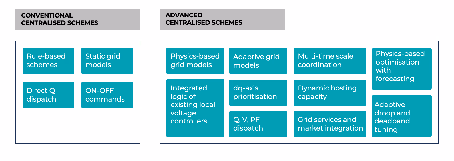
Key features of advanced centralised schemes include:
- Physics-based grid models – Capturing the real electrical behaviour of feeders, rather than relying on over-simplified approximations. These models allow central controllers to predict how voltage will evolve across the network and dispatch actions accordingly.
- Adaptive grid models – Continuously updating parameters (impedances, topology, load profiles) to reflect the true operating state of the grid, enabling resilient and accurate control in the face of uncertainty.
- Multi-time scale coordination – Harmonising the fast responses of inverter-based DERs with the slower dynamics of OLTCs, capacitor banks, and voltage regulators, ensuring stability instead of conflict.
- Physics-based optimisation with forecasting – Leveraging predictive analytics, such as solar and load forecasts, to anticipate voltage issues and act preventively rather than reactively.
- Integrated logic of existing local voltage controllers – Recognising that DERs, and other assets already have embedded control functions, and incorporating them into system-wide optimisation instead of overriding them.
- dq-axis prioritisation – Controlling active and reactive power dispatch in a coordinated manner, ensuring that real and reactive power contributions are prioritised depending on grid conditions.
- Q, V, PF dispatch – Providing flexible dispatch of reactive power (Q), voltage setpoints (V), and power factor (PF) targets to resources, enabling granular control of grid conditions.
- Dynamic hosting capacity – Continuously evaluating how much additional DER capacity can be safely integrated without breaching voltage or thermal limits, and adjusting setpoints accordingly.
- Grid services and market integration – Extending voltage control beyond pure technical compliance, enabling DERs to also provide ancillary services and participate in flexibility markets under the same control framework.
- Adaptive droop and deadband tuning – Dynamically adjusting inverter droop curves and deadbands based on feeder characteristics, preventing oscillations and optimising response to local voltage deviations.
Is Voltage and reactive power support a real problem?
Voltage and reactive power management is often treated as an engineering detail, but recent large-scale events show that it can be the trigger for system-wide failures. A striking example is the Iberian blackout of April 28, 2025, when cascading instabilities led to the collapse of the entire Spanish and Portuguese grid within seconds.
The incident began with forced oscillations at a photovoltaic plant in Badajoz, which propagated through the system and created sustained 0.6 Hz and 0.2 Hz oscillations. These disturbances coincided with rapid changes in solar output and interconnection schedules, driving fluctuations of up to 30 kV in the 400 kV network.
While the transmission system voltages remained formally within limits, the distribution level response became critical. Tap changers at several substations (e.g., in Zaragoza and Granada) did not adapt quickly enough, causing inappropriate trips of transformers and generators. At the same time, the distribution grid was injecting large amounts of reactive power back into the transmission network — 760 MVar nationwide, with concentrations in Madrid and Valencia — further amplifying local and regional voltage swings.
The combination of events — loss of dynamic voltage control from renewable, cogeneration, and waste (RCW) generation, premature disconnections at the distribution–transmission interface, and cascading generator trips — created a domino effect. Within less than 30 seconds, more than 2 GW of generation was lost, reactive power absorption collapsed, and voltages spiralled upward, leading to a total blackout across the Iberian Peninsula .
This case highlights that voltage stability is no longer just a transmission issue.
Distribution-level dynamics such as inverter controls, tap changer settings, reactive injections, can play a decisive role in either stabilising or destabilising the bulk system. As DER penetration rises, the Iberian blackout is a stark reminder that poorly coordinated reactive power support can bring down entire national grids.
Towards Coordinated Voltage Control
The lessons from system-wide failures like the Iberian blackout are clear: voltage and reactive power management is no longer a secondary concern—it is a foundational pillar of modern grid stability. As DERs continue to proliferate across distribution networks, coordinating their reactive and active power behaviour becomes essential for avoiding instability and unlocking the full potential of decentralised energy systems.
To illustrate the benefits of coordinated control in practice, Figure 8 shows a real-world comparison between two operational strategies from SMPnet’s Omega suite platform. On the left, a scenario with only local voltage controls is depicted. In this case, inverter-based DERs operate autonomously using pre-programmed control curves such as Volt-VAR or constant power factor. With no system-wide coordination, these devices act independently, leading to wide voltage variability, excessive reactive power consumption (49.4 MVAr), and multiple tap changer operations (four adjustments across the day).
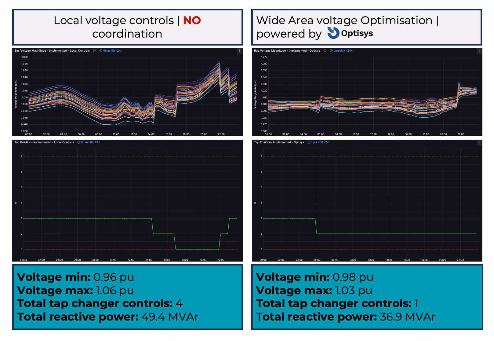
In contrast, the right side demonstrates the impact of SMPnet’s Optisys module—a wide-area voltage optimisation engine integrated into the Omega suite. Optisys centrally orchestrates reactive power dispatch across the grid, coordinating inverters and grid-side devices using predictive optimisation. The benefits are immediate: narrower voltage bands (0.98 to 1.03 pu), reduced total reactive power usage (36.9 MVAr), and only one OLTC tap operation across the full 24-hour period.
These results demonstrate how local control, while scalable and fault-tolerant, lacks the holistic view needed for optimal grid performance. Without coordination, DERs may overcompensate or interact destructively—each acting correctly from a local perspective but harming overall system stability.
Centralised orchestration, as delivered through Optisys, addresses this by:
- Sequencing control actions across time scales to prevent overlap between fast inverter responses and slow OLTC movements.
- Minimising unnecessary reactive power dispatch, reducing energy losses and thermal stress.
- Optimising tap operations, extending asset life and reducing mechanical wear.
- Maintaining voltage within tighter bounds, improving power quality for end users.
Ultimately, coordinated voltage control isn’t just a technical upgrade, it is an enabler for higher hosting capacity, better asset utilisation, and a more resilient, decarbonised grid.
Related